| |
|
|
|
|
Thursday, August 13, 2020 09:07 PM
Rachakonda Balaraju Profile
E-mail:r.balaraju@gmail.com
Mobile: +265 996639468
Digital Clock with college bell by using digital IC's:
Digital Clock with college bell by using digital IC's:(24h /12h Digital clock using ic555 ,7490 decade counters and 7447 bcd-7seg decoders)
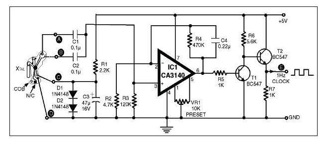
Step 1: 1Hz clock pulse generator
Usually the circuits for generation of 1Hz clock for applications in digital clock and counter circuits make use of ICs in conjunction with a crystal and trimmer capacitors, etc. However, similar or better accuracy can be achieved using a chip-on-board (COB) device found inside a digital clock, which is readily available. This COB consists of IC, capacitors and quartz crystal, etc which are mounted on its surface. It works on 1.4 volt DC source. This COB can be used to derive 1Hz clock.
Resistor R1, capacitor C3, diodes D1 and D2 shown in the circuit convert 5V DC into 1.4V DC. A ˝Hz clock is available at terminals A and B with a phase difference of 90 degrees. The two outputs, are combined using capacitors C1 and C2 to obtain a complete 1Hz clock. This 1Hz clock pulse has a very low amplitude of the order of a few milli-volts which cannot be used to drive the digital circuits directly. This low-level voltage is amplified several times by op-amp IC CA3140.
The op-amp CA3140 is connected in a non-inverting mode, and its gain is set by resistors R4 and R3. Capacitor C2 reduces the AC gain and unwanted stray pick-up and thus improves stability of the circuit. The input impedance of IC CA3140 is very high and thus there is no drop at the input when 1Hz clock signal of low level is connected across its input terminals from the COB. Amplified 1Hz clock pulse is available at its output pin 6, which is further amplified by transistors T1 and T2 to drive the digital clocks and timers.
Precision 1Hz clock Generator using Chip-On-Board
Step 2: Digital logic board to count the clock pulse
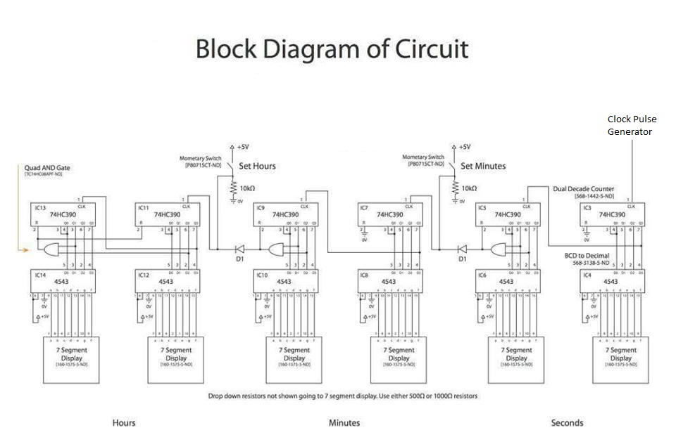
The main parts of the circuit are as follows:
1- 1hz Clock pulse generator: Responsible for generating the clock pulses for the counters, the frequency of the output should be 1 hz which means 1 second for each pulse.
2- Counters: Responsible for generating the time in BCD (Binary Coded decimal).
3- Decoders : Takes the BCD of the counter as input and produces 7 segment output .
4- 7 segments : Displays the time, of course!
* Seconds have 2 displays , 2 decoders and 2 counters. The same for minutes and hours.
To be update soon ...
three Campus Network intranet & Wifi for campus
Server Installation, Intranet, and Digital Smart Boards
Copyright © Rachakonda Balaraju.